Low noise Amplification of a Continuous variable Quantum State
Introduction
Continuous-variable quantum key distribution (CVQKD) provides a secret key shared between the sender (Alice) and the receiver (Bob) with information-theoretical security1,2, which is very suitable for broadband metropolitan and access networks due to its inherent advantages of high key rate and good compatibility with commercial off-the-shelf components3,4,5. However, the reported CVQKD systems with several Mbps secret key rate (SKR)6,7 are still not up to the requirements of one-time-pad encryption (e.g., high-speed secure access networks). Therefore, the development of ultra-high SKR CVQKD is of great importance for its practical application8,9.
According to the modulation method of the coherent state, two practical CVQKD schemes have been proposed. One is based on Gaussian modulation coherent state (GMCS)2,10,11, and the other is based on discrete modulation coherent state (DMCS)12,13,14. The GMCS CVQKD has made great progress in both theory and experiment in recent years15,16,17,18,19 (e.g., see sec. VII and sec. VIII in ref. 18 for an overview). However, the high-rate GMCS modulation/detection practically requires high-speed digital-to-analog converter (DAC) and analog-to-digital converter (ADC) with higher linearity to quantify large amplitude range following Gaussian distribution, which potentially limits the SKR. As a comparison, the DMCS CVQKD, such as four-state protocol, has more practical advantages of working at low signal to noise ratio (SNR) and low linearity in large operating bandwidth, which can improve the SKR significantly20,21,22. Currently, high-speed DMCS CVQKD has been extensively researched by combining the local local oscillator (LLO) scheme, which is free from the security loopholes and the intensity bottleneck of the transmitting LO23,24,25,26,27. However, to improve the SKR in practice, the DMCS LLO-CVQKD system faces the following issues: (1) A precise phase noise compensation (PNC) scheme is required to achieve good coherence between two independent lasers in LLO-CVQKD system28,29,30. Meanwhile, the DMCS CVQKD with large operating bandwidth needs robust approaches to eliminate other excess noises, such as photon-leakage noise, modulation and detection noise and quantization noise29,31. (2) The SKRs of the reported experimental results are mostly evaluated by the linear channel assuming (LCA) security analysis method32,33,34, which restricts the possible attacks performed by the eavesdropper (Eve). Therefore, a more general secure analysis theory against general collective attacks is required to estimate SKR, such as the user-defined security analysis method12, the semidefinite programming (SDP) method35,36,37. (3) The demonstrated DMCS LLO-CVQKD experiments lack a high-efficient and high-speed post-processing setup to extract the final key from the raw key efficiently, which limits its practical application38,39,40.
In this paper, we demonstrate a sub-Gbps key rate four-state DMCS LLO-CVQKD system experimentally within metropolitan area. In the demonstrated quantum key transceiver, the weak quantum signal and the intense pilot tone are independently generated in different optical paths, transmitted in different frequency bands and orthogonal polarization, and separately detected by two independent balanced homodyne detectors (BHDs). Compared with previous DMCS CVQKD setups, our scheme effectively reduces the modulation noise and DAC quantization noise in quantum state preparation, the photo-leakage noise in co-fiber transmission, the detection noise and ADC quantization noise in simultaneous detection. Moreover, a precise fast-slow PNC scheme to eliminate the dominate phase noise, including the pilot-tone-assisted fast-drift phase recovery and the least mean square (LMS) adaptive slow-drift phase recovery, is innovatively proposed and efficiently realized for achieving an ultra-low level of excess noise in experiment. Besides, a high-efficient post-processing setup is designed to achieve rate-adaptive reconciliation efficiency better than 95% and practically extract the final secure keys in experiment. Based on the above key technological breakthroughs, the SKRs of the demonstrated CVQKD setup are 190.54 Mbps@5 km, 133.6 Mbps@10 km, and 52.48 Mbps@25 km with the LCA security analysis method and 233.87 Mbps@5 km, 137.76 Mbps@10 km, and 21.53 Mbps@25 km with the SDP security analysis method, achieving a single-carrier CVQKD with sub-Gbps key rate within metropolitan area.
Results
Experimental setup
The experimental setup of the proposed four-state discretely modulated LLO-CVQKD scheme is demonstrated in Fig. 1. At Alice's site, a continuous optical carrier is divided into two optical paths by a beam splitter (BS). The upper optical carrier is modulated by the quadrature phase-shift keying (QPSK) digital signal with R sym = 5 GBaud symbol rate in an in-phase/quadrature (IQ) modulator (FUJITSU FTM7962EP), where the digital signals I s (t) = real{[I(t) +jQ(t)]exp(j2πf s t)} and Q s (t) = imag{[I(t) +jQ(t)]exp(j2πf s t)} are generated from a high-speed arbitrary waveform generator (AWG, Keysight M8195A) with a single channel sampling rate of 30 GSa s−1. The security of QPSK modulation with a carrier f s is theoretically equivalent to that of QPSK with baseband modulation24,28,30,32. Moreover, the bandwidth and amplitude of the QPSK signal from the AWG should be carefully controlled for well matching linear gain of broadband amplifier and ensuring the IQ modulation without distortion. In our experiment, the DAC amplitude is properly set to 320 mV. The QPSK bandwidth is further reduced by the root-raised cosine filter with a roll-off factor a ro = 0.3 without the influence on the phase recovery accuracy in digital signal processing (DSP). The QPSK modulated signal is then attenuated by a variable optical attenuator (VOA) to be four-state discretely modulated quantum signal. The corresponding average number of photons per pulse is 0.47 with the quantum optical power of −65.2 dBm and frequency of 193.5 THz. From Fig. 1, the polarization controller 1 (PC1) is used to maintain the polarization direction of the quantum signal and ensure the optimal modulation in the IQ modulator. Meanwhile, PC2 and PC3 are used to align the polarization direction and optical power of the pilot tone and the LO signal, respectively. The lower optical carrier is directly attenuated to be a pilot tone with reasonable amplitude. The prepared quantum signal and pilot tone with different frequency bands and orthogonal polarization are transmitted through the quantum channel (single mode fiber with a wavelength of 1550 nm) and separated by a polarization beam splitter (PBS) at Bob's site. In order to separate the quantum signal and pilot tone efficiently, a polarization synthesis analyzer (PSA, General Photonics PSY-201) is used for correcting the polarization deterioration resulted from the fiber channel disturbance. Subsequently, the quantum signal and pilot tone are respectively detected with LLO signals by two commercial BHDs (Optilab BPR-23-M). In our experiment, the optical carrier at Alice's site and the LLO signal at Bob's site are independently generated from two free-running lasers (NKT Photonic Basik E15). Moreover, two BHDs' output signals are collected and digitized by a high-speed oscilloscope (Keysight DSOV084A) for the subsequent DSP and post-processing.
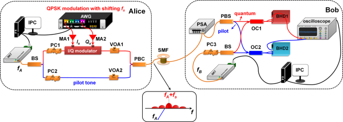
LLO-CVQKD continuous-variable quantum key distribution with local local oscillator, BS beam splitter, PC polarization controller, AWG arbitrary waveform generator, MA microwave amplifier, PSA polarization synthesis analyzer, VOA variable optical attenuator, PBC polarization beam combiner, SMF single mode fiber, PBS polarization beam splitter, OC optical coupler, BHD balanced homodyne detector, IPC industrial personal computer.
In the proposed four-state LLO-CVQKD system, the intense pilot tone and the weak quantum signal are independently generated in different optical paths, which is beneficial to improve the preparation accuracy of the quantum state in the case of finite DAC quantization bits and modulation extinction ratio, so that the DAC quantization noise and modulation noise can be well reduced compared with the conventional RF-subcarrier-assisted LLO-CVQKD scheme as in Eqs. (17) and (18). Moreover, the upper optical carrier is shifted by frequency f s = 3.5 GHz in 5 GBaud QPSK modulation relative to the lower optical carrier at Alice's site, where the photo-leakage noise from intense pilot tone to weak quantum signal can be eliminated in co-fiber transmission due to their complete isolation in frequency domain as in Eq. (19). In experiment, the shifting frequency f s is mainly determined by the quantum operating bandwidth Δf q =R sym*(1 +a ro) and the laser frequency difference Δf AB. At Bob's site, the intense pilot tone and weak quantum signal are separated in orthogonal polarization state for fully guaranteeing low-noise coherent detection of broadband quantum signal and high-saturation limitation detection of intense pilot tone. Moreover, referenced to Eqs. (20) and (21), the detection noise and ADC quantization noise can be further reduced by separately detecting the intense pilot tone and weak quantum signal in the case of the limited detection dynamic and ADC quantization bits. As shown in Fig. 2a, b, the designed QPSK quantum frequency component and the designed pilot component are in different frequency bands, verifying no crosstalk between quantum signal and pilot tone. Meanwhile, in Fig. 2a, the pilot tone is not completely suppressed due to the PBS with finite polarization isolation ratio, while the residual pilot tone has no impact on the extraction of the quantum signal in completely different frequency band.
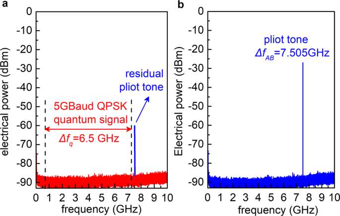
a BHD1's output quantum frequency spectrum. b BHD2's output pilot frequency spectrum. Δf q = 6.5 GHz is bandwidth of the desired quantum signal and Δf AB = 7.505 GHz is the frequency of pilot tone. QPSK quadrature phase-shift keying, BHD balanced homodyne detector.
Precise fast-slow phase noise compensation
In order to realize a reasonably low excess noise, a precise fast-slow PNC scheme is designed and realized in DSP to accurately compensate the dominate phase noise. As is illustrated in Fig. 3, the output electrical signals i sig(t) and i pilot(t) of two BHDs are digitized by dual-channel 8 bit ADCs at 40 GSs−1, respectively. Firstly, the pilot tone Δf AB is precisely estimated to be 7.505 GHz by searching the peak value of the pilot frequency spectrum, and the center frequency Δf AB –f s of the desired quantum frequency spectrum is determined to be 4.005 GHz when the shifting frequency f s is 3.5 GHz. By using the estimated frequencies, the desired quantum and pilot signals are band-pass filtered for eliminating the out-of-band noise and orthogonally down-converted for extracting the in-phase and quadrature components in baseband, respectively. Next, the baseband components of QPSK quantum signal and pilot tone are obtained by matching root-raised cosine filtering and the narrow band low-pass filtering, respectively. Note that the quantum filtering bandwidths in DSP are selected based on the detected power, the QPSK quantum symbol rate, the roll-off factor of the root-raised cosine filter and the employed laser linewidth, which requires a compromise between noise suppression and phase estimation accuracy. Therefore, the fast-drift laser phase difference Δφ AB(k) involved in QPSK quantum signal I sig(k) +jQ sig(k) can be recovered by sharing the phase of the pilot tone I pilot(k) +jQ pilot(k). Moreover, the slow-drift phase difference Δφ d (k) of the QPSK quantum signal originated from different fiber delay and disturbance is adaptively recovered by the designed LMS algorithm with 51 tap and 1e−3 step. Besides, the symbol synchronization between the transmitted and received data is finely corrected for further improving the phase recovery accuracy. Furthermore, the optical-frequency difference of two free-running lasers is fixed as much as possible by precise laser wavelength control in our experiment, while the influence of small optical-frequency deviation can be eliminated by the adaptive filtering in the designed DSP. To verify the proposed DSP, the constellation diagrams of the detected QPSK quantum signal without and with the phase recovery are demonstrated respectively under transmission distance L = 25 km, as shown in Fig. 3a, b.
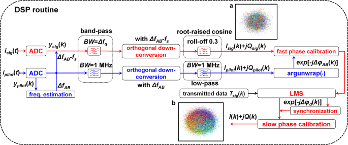
a constellation diagrams of QPSK quantum signal without phase recovery in the case of transmission distance L = 25 km. b constellation diagrams of QPSK quantum signal with phase recovery in the case of transmission distance L = 25 km. LLO-CVQKD continuous-variable quantum key distribution with local local oscillator, DSP digital signal processing, QPSK quadrature phase-shift keying, ADC analog-to-digital converter, LMS least mean square, BW bandwidth, freq. estimation: frequency estimation.
High-efficient post-processing
To extract the final key efficiently, a high-efficient post-processing setup is designed as follow. Since the SNR is very low in our experiment, the raw keys after DSP, which are essentially correlated random data, are firstly reversely reconciled with the multidimensional reconciliation method38. After the reconciliation, the raw keys of Alice and Bob are both transferred into binary sequences, which are unidentical due to inevitable noise and will be further corrected by employing the error correction matrix based on multi-edge-type low-density parity check (MET-LDPC) method41,42,43. Note that in order to guarantee the extraction of the final key in our experiments and hence validate the practicality of the high SKR CVQKD system proposed in this paper, the reconciliation efficiency should be achieved as high as possible. Thus, three parity check matrixes are correspondingly designed for the experiments under the transmission distance of 5, 10, and 25 km with a code rate of 0.07, 0.06, and 0.03, respectively, as shown in Table 1. Specially, for the design of the matrixes, a 10 bit quantization based on density evolution algorithm is chosen to obtain the degree distribution functions under such low SNRs, through which the convergence threshold \({\sigma }_{{DE}}^{* }\)of degree distribution function and the corresponding threshold reconciliation efficiency β σ required by the demonstrated CVQKD system is guaranteed. Subsequently, the layered LDPC decoder algorithm39 and the adaptive decoding algorithm40 are combined for error correction step. After the error correction, privacy amplification with Toeplitz matrix is employed to extract the final keys44,45,46. It can be observed from Table 1 that the threshold reconciliation efficiency β σ and the efficient rate-adaptive reconciliation efficiency β a are both gained to be better than 95% over the distance of 5, 10, and 25 km. Moreover, the SNRs and reconciliation efficiencies without rate-adaptive versus frame error rates (FERs) are computed under the three code rates and shown in Fig. 4, for further verifying our designed post-processing setup. For our post-processing, the high-efficient check matrixes are innovatively designed and efficiently realized on graphics processing unit (GPU, NVIDIA TITAN Xp) with low SNR and final secure keys are successfully extracted in off-line situation, which are experimentally achieved in the four-state LLO-CVQKD system compared with the reported literatures according to our knowledge. Note that it is significant for high-rate CVQKD system to distribute the final secure keys between two legitimate parts by post-processing in real time, which will be deeply researched in our future work.
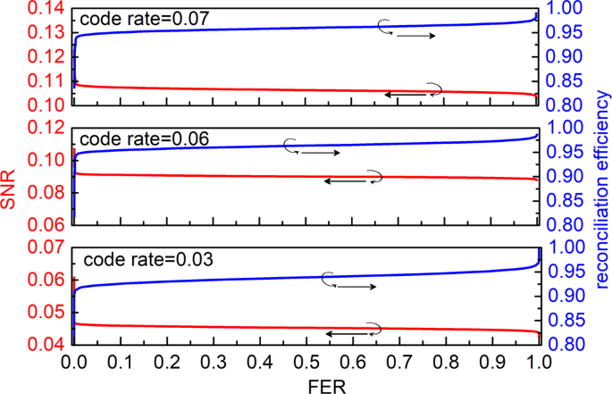
SNRs and reconciliation efficiencies are experimentally measured at code rate of 0.07, 0.06 and 0.03, respectively. SNR signal to noise ratio, FER frame error rate.
Discussion
The performance of the proposed four-state LLO-CVQKD setup is shown as follows. In our work, the SKRs of the demonstrated experimental four-state LLO-CVQKD system are firstly evaluated by the general SDP security analysis method35 and then verified by the frequently used LCA security analysis method13. Note that the SDP method depends on a lot of computational power for realizing the optimal solution of Z. In the latest work, an improved SDP method has been reported for obtaining Z by explicit solution36. Nevertheless, the SKR with explicit solution is equal to SKR with SDP. For achieving an optimized SKR, the SKR as a function of the excess noise and modulation variance are simulated theoretically for choosing an modulation variance in applicable for the SDP and LCA method. As shown in Fig. 5a, b, a preferable modulation variance V A is chosen to be about 0.45 in shot noise unit (SNU) for supporting a better SKR. The modulation variance can be correctly controlled by carefully stabilizing the bias of IQ modulator with an ultra-high precision bias controller (MBC-IQ-03) and the power of quantum signal with a high-performance VOA (EXFO LTB) in our experiment.
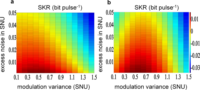
The simulated results are obtained in the case of secure transmission distance of 25 km. a SKR is evaluated with SDP method. b SKR is evaluated with LCA method. SNU shot noise unit, SKR secret key rate, SDP semidefinite programming, LCA linear channel assuming.
With the modulation variance V A = 0.456 SNU, the symbol rate R sym = 5 GBaud, the BHD's quantum efficiency η = 0.45 and transmission distance L = 25 km in our experiment, several main excess noise components are estimated based on the excess noise model of four-state LLO-CVQKD setup in the "Methods" section and the experimental measurements, which are summarized in Table 2. From Table 2, the total excess noise excluding trusted electronic noise is experimentally estimated to 0.0075, and it is regarded as untrusted noise for evaluating the SKR in our work. The other noise of 0.0033 in Table 2 might be considered and originated from the instability of the experimental setup, such as the bias drifting of the IQ modulator and the unreal-time polarization correction of the PSA. Moreover, the trusted electronic noise υ el including detection noise ε Det and ADC quantization noise ε ADC is estimated to be 0.297 in our experiment. From this, the experimental detection noise ε Det is ~0.2869 due to small ADC quantization noise ε ADC considered in excess noise model. Compared with the theoretical detection noise ε Det, the difference might be caused by the finite common mode rejection ratio (CMRR) and the instability of the employed BHD.
Under the trusted electronic noise model, the corresponding measured excess noises are estimated on the block of size 4 × 10⁶ over transmission distance of 5, 10, and 25 km, respectively, as shown in Fig. 6. The excess noise thresholds of null SKR at 5, 10, and 25 km are determined to be 0.0176, 0.0141, and 0.0092 for SDP method and 0.0563, 0.0497, and 0.0371 for LCA method, respectively. Note that the tolerable excess noise by the SDP method is lower than the LCA method, which indicates that it relies on more accuracy excess noise suppression in practical setup. The mean excess noises shown in Fig. 6 are 0.0072, 0.0073, and 0.0075 over transmission distance of 5, 10, and 25 km, respectively, achieving ultra-low level of excess noise. According to the means of measured excess noises and the obtained rate-adaptive reconciliation efficiency β a in Table 1, the corresponding asymptotic SKRs are 233.87 Mbps/190.54 Mbps, 137.76 Mbps/133.6 Mbps and 21.53 Mbps/52.48 Mbps with the SDP/LCA methods for transmission distance of 5 km, 10 km and 25 km, respectively, as is demonstrated in Fig. 7. For highlighting our work, we make a full comparison between the proposed LLO-CVQKD scheme and the existing literatures, as shown in Table 3. We can see from Table 3 that our work evaluates the SKR with the LCA and SDP methods, achieving a level of sub-Gbps SKR in asymptotic regime. Moreover, compared with previous works, the SKR of our work is significantly improved by increasing the repetition rate up to 5 GBaud, optimizing the excess noise to an ultra-low level and realizing the reconciliation efficiency better than 95%.
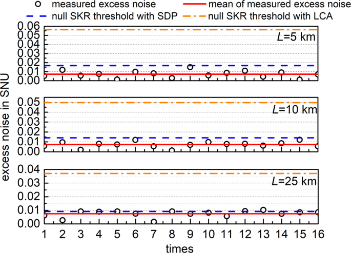
The results are measured by 16 times over 5, 10, and 25 km secure transmission distance, respectively. The black circles represent the measured excess noises on the block of size 4 × 10⁶, the red solid lines define the mean of the measured excess noises, the blue dash lines and the orange dash dots denote the excess noises of null SKR threshold with SDP and LCA methods, respectively. SNU shot noise unit, SKR secret key rate, SDP semidefinite programming, LCA linear channel assuming.
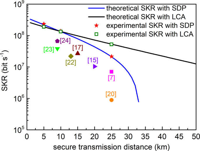
The blue and black lines represent the simulated SKRs at different secure transmission distances with the SDP and LCA method. The red star and the olive square correspond experimental SKRs with the SDP and LCA method, respectively. The numbers in the square brackets represent the corresponding refs. [[7,15,17,20,22,23,24,]]. SKR secret key rate, SDP semidefinite programming, LCA linear channel assuming.
The proposed four-state LLO-CVQKD scheme can be experimentally demonstrated with high repetition rate and high SKR by mainly relying on low-noise high-speed transceiver, more precise fast-slow PNC scheme and high-efficient post-processing due to the lower SNR in high-rate LLO-CVQKD. Moreover, in contrast to ref. 35, the SKR evaluated by the LCA method is lower than that of the SDP method within transmission distance of 10 km, because the LCA method considers the trusted receiver (BHD and ADC) in our work. Significantly, the additional side channels in IQ modulation are susceptible to leakage of secret information47, so the sideband modulation should be filtered out in the practical CVQKD system. Finally, the obtained ultra-low level of excess noise in the proposed four-state LLO-CVQKD also can support the SKR evaluation under finite-size effect when four-state CVQKD with tight finite-size security is reported in future. At the same time, our future work will expand four-state modulation to larger constellations or Gaussian modulation for increasing the SKR and transmission distance of LLO-CVQKD. More importantly, the ultra-low level of excess noise, the high-efficient reconciliation efficiency better than 95%, and the more general secure analysis by SDP method are experimentally demonstrated in this paper, achieving high-rate and more secure four-state LLO-CVQKD system for high-speed metropolitan area network application.
Conclusion
We have experimentally demonstrated a sub-Gbps key rate four-state discretely modulated LLO-CVQKD scheme within metropolitan area. In the proposed scheme, the quantum signal and pilot tone are independently generated, co-propagated and separately detected based on frequency- and polarization-multiplexing method, which effectively reduces the modulation noise, ADC/DAC quantization noise, detection noise and photon-leakage noise. Moreover, the dominate phase noise can be precisely eliminated by the designed fast-slow PNC scheme based on pilot-tone-assisted fast-drift phase recovery and LMS adaptive slow-drift phase recovery, achieving a 5 GBaud symbol rate four-state LLO-CVQKD with an ultra-low excess noise. Furthermore, a high-efficient post-processing with the rate-adaptive reconciliation efficiency better than 95% is designed to extract the final secure key experimentally (off-line), i.e., 233.87 Mbps, 137.76 Mbps and 21.53 Mbps by the SDP method and 190.54 Mbps, 133.6 Mbps and 52.48 Mbps by the LCA method over transmission distance of 5, 10, and 25 km, respectively, which allows the sub-Gbps SKR single-carrier CVQKD within metropolitan area. In our work, the SDP method, which is resistant against general collective attack, is firstly used to evaluate the SKR of the experimental DMCS CVQKD setup. Moreover, the high-rate metropolitan QKD will be implemented in practice by further increasing the post-processing rate and the coherent stability of quantum key transceiver with LLO in the future. More importantly, the LLO-CVQKD with ultra-high SKR is realized to pave the way for the one-time pad encryption in secure broadband metropolitan and access networks.
Methods
Four-state LLO-CVQKD protocol
The four-state CVQKD protocol can be described as follows. At Alice's site, as shown in Fig. 8, a string of random bits x = (x 0, …, x 2L−1) are encoded as coherent states |ψ k 〉 with equal probability35
$$|{\psi }_{k}\rangle :=|{i}^{k}\alpha \rangle ={e}^{-{\alpha }^{2}/2}\mathop{\sum }\limits_{n\ge 0}{e}^{i(2k+1)n(\pi /4)}({\alpha }^{n}/\sqrt{n!})|n\rangle$$
(1)
with α > 0 and k∈ {0, 1, 2, 3}. After transmission over an insecure quantum channel, the prepared coherent states are measured by heterodyne detection at Bob's site with measurement results z = (z 0, …, z 2L−1)∈ ℝ 2L , which is converted into a raw key y = (y 0, …, y 2L−1), given by
$$\left({y}_{2l-1},{y}_{2l}\right)=\left\{\begin{array}{l}\left(1,\,1\right)\quad\quad{{{{{\mathrm{when}}}}}}\,{z}_{2l-1}\,\,\ge 0,\,{z}_{2l} \; > \; 0 \hfill\\ \left(-1,\,1\right)\quad\,{{{{{\mathrm{when}}}}}}\,{z}_{2l-1} \; < \; 0,\,{z}_{2l}\ge 0\hfill\\ \left(-1,\,-1\right)\;\,{{{{{\mathrm{when}}}}}}\,{z}_{2l-1}\,\le\, 0,\,{z}_{2l} \; < \; 0 \hfill\\ \left(1,\,-1\right)\quad\,{{{{{\mathrm{when}}}}}}\,{z}_{2l-1} \; > \; 0,\,{z}_{2l}\;\le\; 0 \hfill\end{array}\right.$$
(2)
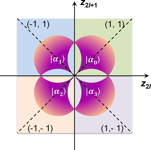
The four quadrants with different colors represent the four encoded coherent states sent from Alice's site, respectively. The first quadrant (1, 1) denotes the coherent state encoded with phase of π/4, the second quadrant (−1, 1) denotes the coherent state encoed with phase of 3π/4, the third quadrant (−1, −1) denotes the coherent state encoded with phase of 5π/4 and the fourth quadrant (1, −1) denotes the coherent state encoded with phase of 7π/4.
Then, the parameter estimation is performed to calculate how much secret key can be achieved from the raw key via post-processing. The post-processing process includes reverse reconciliation, error correction and privacy amplification. In the asymptotic limit, the SKR with reverse reconciliation can be written as
$$R={R}_{{{{{{\mathrm{sym}}}}}}}(\beta {I}_{{{{{{\mathrm{AB}}}}}}}-{S}_{{{{{{\mathrm{BE}}}}}}})$$
(3)
where I AB is the Shannon mutual information between Alice and Bob, and S BE is the Holevo bound between Bob and Eve, respectively. Currently, the security proofs of CVQKD with four-state modulation have been established by LCA method13 and SDP method35,36. In most reported four-state LLO-CVQKD experiments, the LCA method is used to evaluate the SKR, which limits the attack of Eve. Meanwhile, the SDP method is applicable for general collective attacks. However, the tolerable excess noise with SDP method is very low (e.g., 0.01 SNU), which is challenging in practical CVQKD system. In our work, the SDP method is verified experimentally with reasonably low excess noise.
Security analysis with LCA method
For the LCA method, the I AB in Eq. (3) can be expressed as13,34
$${I}_{{{{{{\mathrm{AB}}}}}}}={\log }_{2}\frac{V+{\chi }_{{{{{{\mathrm{line}}}}}}}+{\chi }_{{{{{{\mathrm{het}}}}}}}/T}{1+{\chi }_{line}+{\chi }_{{{{{{\mathrm{het}}}}}}}/T}$$
(4)
with
$$V={V}_{{{{{{\mathrm{A}}}}}}}+1$$
(5a)
$${\chi }_{{{{{{\mathrm{line}}}}}}}=1/T-1+\varepsilon$$
(5b)
$${\chi }_{{{{{{\mathrm{het}}}}}}}=[(2-\eta )+2{\upsilon }_{el}]/\eta$$
(5c)
with the transmittance efficiency T, the modulation variance V A = 2α 2 and the excess noise ε. At the same time, S BE can be calculated as
$${S}_{{{{{{\mathrm{BE}}}}}}}=G\left(\frac{{\lambda }_{1}-1}{2}\right)+G\left(\frac{{\lambda }_{2}-1}{2}\right)-G\left(\frac{{\lambda }_{3}-1}{2}\right)-G\left(\frac{{\lambda }_{4}-1}{2}\right)$$
(6)
where the Von Neuman entropy G(x) = (x + 1)log2(x + 1) −xlog2(x), and symplectic eigenvalues λ i can be derived from the covariance matrix between Alice and Bob, which are expressed as,
$${\lambda }_{1,2}=\sqrt{\frac{1}{2}\left(A\pm \sqrt{{A}^{2}-4B}\right)}$$
(7a)
$${\lambda }_{3,4}=\sqrt{\frac{1}{2}(C\pm \sqrt{{C}^{2}-4D})}$$
(7b)
with
$$A={V}^{2}+{T}^{2}{(V+{\chi }_{{{{{{\mathrm{line}}}}}}})}^{2}-2T{Z}_{4}^{2}$$
(8a)
$$B={(T{V}^{2}+TV{\chi }_{{{{{{\mathrm{line}}}}}}}-T{Z}_{4}^{2})}^{2}$$
(8b)
$$C=\frac{A{\chi }_{{{{{{\mathrm{het}}}}}}}^{2}+B+1+2{\chi }_{{{{{{\mathrm{het}}}}}}}[V\sqrt{B}+T(V+{\chi }_{{{{{{\mathrm{line}}}}}}})]+2T{Z}_{4}^{2}}{{[T(V+{\chi }_{{{{{{\mathrm{line}}}}}}}+{\chi }_{{{{{{\mathrm{het}}}}}}}/T)]}^{2}}$$
(8c)
$$D=\frac{{(V+{\chi }_{het}\sqrt{B})}^{2}}{{[T(V+{\chi }_{line}+{\chi }_{het}/T)]}^{2}}$$
(8d)
$${Z}_{4}=2{\alpha }^{2}\left({\xi }_{0}^{3/2}{\xi }_{1}^{-1/2}+{\xi }_{1}^{3/2}{\xi }_{2}^{-1/2}+{\xi }_{2}^{3/2}{\xi }_{3}^{-1/2}+{\xi }_{3}^{3/2}{\xi }_{0}^{-1/2}\right)$$
(8e)
where ξ 0,2 = 1/2exp(−α 2)[cosh(α 2) ± cos(α 2)] and ξ 1,3 = 1/2exp(−α 2) [sinh(α 2) ± sin(α 2)].
Security analysis with SDP method. For the SDP method, the I AB in Eq. (3) is expressed as35,36
$${I}_{{{{{{\mathrm{AB}}}}}}}={\log }_{2}\left(1+\frac{2T{\alpha }^{2}}{2+T\varepsilon }\right)$$
(9)
where we have defined the quantum efficiency η = 1 and the electronic noise υ el = 0. The Holevo bound S BE can be simplified as
$${S}_{{{{{{\mathrm{BE}}}}}}}=G\left(\frac{{v}_{1}-1}{2}\right)+G\left(\frac{{v}_{2}-1}{2}\right)-G\left(\frac{{v}_{3}-1}{2}\right)$$
(10)
where v 3 = 1 + 2α 2 − [Z *2/(1 +υ)]. v 1 and v 2 are the symplectic eigenvalues of the optimized covariance matrix between Alice and Bob, given by
$${\varGamma }^{\ast }=\left[\begin{array}{lc}(1+2{\alpha }^{2})I{I}_{2} & {Z}^{\ast }{\sigma }_{z}\\ {Z}^{\ast }{\sigma }_{z} \hfill& \upsilon I{I}_{2}\end{array}\right]$$
(11)
where υ = 1 + 2Tα 2 +Tε. II 2 = diag[1, 1] and σ z = diag[1, −1] are the diagonal matrices. Z is the optimal solution of the following constraint condition
$$ \min {{{{{\rm{tr}}}}}}\left[\left({\prod} a{\prod} {\otimes} b+{\prod} {a}^{{{\dagger}} }{\prod} {\otimes} {b}^{{{\dagger}} }\right)X\right]\\ \left\{\begin{array}{c}{{{{{\rm{tr}}}}}}\Big\{\Big[{\prod} \otimes (1+2{b}^{{{\dagger}} }b)\Big]X\Big\}=\upsilon \hfill\\ {{{{{\rm{tr}}}}}}\Bigg\{\Bigg[\begin{array}{c}(|{\psi }_{0}\rangle \langle {\psi }_{0}|-|{\psi }_{2}\rangle \langle {\psi }_{2}|)\otimes {\hat{q}}\\ +(|{\psi }_{1}\rangle\langle {\psi }_{1}|-|{\psi }_{3}\rangle\langle {\psi }_{3}|)\otimes {\hat{p}}\end{array}\Bigg]X\Bigg\}=2\sqrt{T}\alpha \\ {{{{{\rm{tr}}}}}}({B}_{k,\ell}X)=\frac{1}{4}\langle {\alpha }_{\ell }|{\alpha }_{k}\rangle\hfill \\ X\;\underline{\succ}\;0\hfill\end{array}\right.$$
(12)
with the annihilation and creation operators a (b) and a † (b †) on Fock space at Alice's site and Bob's site, respectively. X is positive semidefinite. We have defined B ℓ, k = |ψ ℓ 〉〈ψ k | (ℓ, k = 0, 1, 2, 3) and Π = |ψ 0〉〈ψ 0 | +|ψ 1〉〈ψ 1 | +|ψ 2〉〈ψ 2 + |ψ 3〉〈ψ 3 | . In the SDP method, the four coherent states can be expressed as
$$|{\psi }_{k}\rangle =\frac{1}{2}\mathop{\sum }\limits_{m=0}^{3}{e}^{-j(2k+1)m\pi /4}|{\phi }_{m}\rangle$$
(13)
where
$$|{\phi }_{m}\rangle =\frac{1}{\sqrt{{\xi }_{m}}}\mathop{\sum }\limits_{n=0}^{\infty }\frac{{\alpha }^{4n+m}}{\sqrt{(4n+m)!}}|4n+m\rangle$$
(14)
with ξ 0,2 = 1/2[cosh(α 2) ± cos(α 2)] and ξ 1,3 = 1/2[sinh(α 2) ± sin(α 2)].
Excess noise model of four-state LLO-CVQKD setup
For distilling the final key with the above-mentioned LCA and SDP methods, the designed four-state LLO-CVQKD system relies on a low level of excess noise. In the proposed four-state LLO-CVQKD scenario, several main excess noise components are considered and modeled as31
$$\varepsilon ={\varepsilon }_{{{{{{\mathrm{RIN}}}}}}}+{\varepsilon }_{{{{{{\mathrm{DAC}}}}}}}+{\varepsilon }_{{{{{{\mathrm{Mod}}}}}}}+{\varepsilon }_{{{{{{\mathrm{LE}}}}}}}+{\varepsilon }_{{{{{{\mathrm{Det}}}}}}}+{\varepsilon }_{{{{{{\mathrm{ADC}}}}}}}+{\varepsilon }_{{{{{{\mathrm{Phase}}}}}}}$$
(15)
where the detection noise ε Det and the ADC quantization noise ε ADC are not attributed to an Eve under the assumptions of trusted receiver (BHD and ADC). Therefore, the detection noise ε Det and the ADC quantization noise ε ADC are regarded as trusted noise in LCA security analysis method31 and are ignored (the quantum efficiency η = 1 and the electronic noise υ el = 0) in SDP security analysis method35.
In Eq. (15), the first term ε RIN represents the laser intensity noise of two independent lasers, which mainly includes two parts
$${\varepsilon }_{{{{{{\mathrm{RIN}}}}}}}={V}_{{{{{{\mathrm{A}}}}}}}\sqrt{{{{{{\mathrm{RI}}}}}}{{{{{{\mathrm{N}}}}}}}_{{{{{{\mathrm{quan}}}}}}}\varDelta {\nu }_{{{{{{\mathrm{A}}}}}}}}+\frac{1}{4T}{{{{{\mathrm{RI}}}}}}{{{{{{\mathrm{N}}}}}}}_{{{{{{\mathrm{LO}}}}}}}\varDelta {\nu }_{{{{{{\mathrm{B}}}}}}}{V}_{{{{{{\mathrm{RIN}}}}}}}(\hat{q})$$
(16)
where RINquan and RINLO are the relative intensity noises (RINs) of the Alice's laser and Bob's laser, respectively, and Δν A and Δν B correspond their laser linewidths. From the specification of the lasers employed in our experiment, both lasers have a RIN of –135dBc@10 MHz and a laser linewidth of <0.1 kHz. Moreover, V RIN(\(\hat{q}\)) =TV A describes the quantum variance without taking the LO's RIN into account. So, the laser intensity noise ε RIN can be calculated to be 8.1 × 10⁻⁵ based on Eq. (16).
The second term ε DAC in Eq. (15) is the quantization noise introduced by the additional voltage error of the quadratures of the signal in finite DAC quantization bits, given by
$${\varepsilon }_{{{{{{\mathrm{DAC}}}}}}}\le {V}_{{{{{{\mathrm{A}}}}}}}{\left[\pi \frac{\delta {V}_{{{{{{\mathrm{DAC}}}}}}}}{{V}_{{{{{{\mathrm{DAC}}}}}}}}+\frac{{\pi }^{2}}{2}{\left(\frac{\delta {V}_{{{{{{\mathrm{DAC}}}}}}}}{{V}_{{{{{{\mathrm{DAC}}}}}}}}\right)}^{2}\right]}^{2}$$
(17)
where V DAC is voltage translated from the signal-bit information. Moreover, the deviation voltage δV DAC is determined to be 0.01 V DAC by the quantization bits and voltage range of DAC. In this case, the DAC quantization noise is computed to be 4.64 × 10⁻⁴ based on Eq. (17).
In Eq. (15), without considering the intense pilot tone, the modulation noise ε Mod can be expressed as48
$${\varepsilon }_{{{{{{\mathrm{Mod}}}}}}}={|{a}_{S}|}^{2}{10}^{-{d}_{{{{{{\mathrm{dB}}}}}}}/10}$$
(18)
where d dB represents the extinction ratio of the employed IQ modulator and a S means the amplitude of the quantum signal. Since the weak quantum signal and the intense pilot tone are separately prepared in our scheme, the modulation noise ε Mod can be calculated based on Eq. (18), which is 4.7 × 10⁻⁴ with the d dB = 40 dB and the quantum optical power of −65.2 dBm. It is obvious from Eqs. (17) and (18) that the quantization noise ε DAC and modulation noise ε Mod are lower relative to the reported RF-subcarrier-assisted LLO-CVQKD scheme26,27 due to the weak quantum signal and intense pilot tone generated in different modulation path.
The fourth term ε LE in Eq. (15) denotes the photon-leakage noise, which is determined as48,49
$${\varepsilon }_{{{{{{\mathrm{LE}}}}}}}=\frac{2{|{a}_{R}|}^{2}}{{R}_{e}}$$
(19)
with the pilot amplitude a R . R e denotes the isolation ratio, and it mainly depends on polarization isolation ratio and modulation extinction ratio when the quantum signal and pilot tone are in same time duration or frequency band based on time multiplexing or frequency multiplexing. In the former LLO-CVQKD schemes, the surplus pilot signals cannot be completely suppressed due to finite modulation extinction ratio and polarization isolation ratio, resulting in photon-leakage noise on the quantum signal in practical experiment7,48. Therefore, it is better to completely isolate the quantum signal and pilot tone in frequency or time domain. In our scheme, the photon-leakage noise ε LE from the intense pilot tone to the weak quantum signal can be eliminated due to their complete separation in frequency domain.
From Eq. (15), the fifth term ε Det represents the heterodyne detection noise at Bob's site, given by
$${\varepsilon }_{{{{{{\mathrm{D}}}}}}{{{{{\rm{et}}}}}}}=2\frac{{{{{{\mathrm{NE}}}}}}{{{{{{\mathrm{P}}}}}}}^{2}}{\hslash f}\frac{B\tau }{{P}_{{{{{{\mathrm{LO}}}}}}}}+{\varepsilon }_{{{{{{\mathrm{LF}}}}}}}$$
(20)
with the noise-equivalent power NEP and Planck's constant ħ. f and P LO are the LO frequency and power, and they are 193.5 THz and 4 dBm, respectively, in our experiment. τ denotes the pulse duration and B represents the effective detection bandwidth. Note that an additive noise ε LF denotes the low-frequency quantum noise, which is mainly determined by the low-frequency linearity of BHD and the linewidth of laser. Since the linewidth of the employed lasers is very low (<0.1 kHz) and the demodulation signal is moved to intermediate frequency (about 4 GHz) in our scheme, the low-frequency quantum noise ε LF is extremely low, which can be ignored. Therefore, the heterodyne detection noise ε Det can be theoretically calculated to be 0.2714 based on Eq. (20) in the case of the pulse duration τ = 0.2 ns, the effective detection bandwidth B = 6.5 GHz and the NEP = 5.8 pW Hz−1/2.
In the heterodyne detection case, the ADC quantization noise ε ADC in Eq. (15) can be expressed as
$${\varepsilon }_{{{{{{\mathrm{ADC}}}}}}}=2\frac{\tau }{\hslash f{C}_{g}{P}_{{{{{{\mathrm{LO}}}}}}}}\frac{1}{12}\frac{{R}_{U}^{2}}{{2}^{2n}}$$
(21)
where C g is the conversion gain of the BHD (in V W−1). R U and n are the full voltage range and quantization bits of ADC, respectively. In our experiment, the conversion gain C g is 1500 V W−1 typ. from the specification of the employed BHD. The full voltage range R U and ADC quantization bits n of the oscilloscope are set to 120 mV and 8 bits, respectively. Based on Eq. (21), the ADC quantization noise can be calculated to be 0.0101. Therefore, according to the calculated detection noise ε Det and ADC quantization noise ε ADC, the electronic noise υ el is theoretically calculated to be 0.2815 close to the measured electronic noise of 0.297 in our experiment. Meanwhile, it is regarded as the trusted noise for the LCA method and ignored for the SDP method in our work. It is obvious that the ADC quantization noise will be alleviated in finite quantization bits if the weak quantum signal and intense pilot tone are independently quantized by two ADCs at Bob's site. Moreover, we can see from Eqs. (20) and (21) that the separate detection can flexibly provide the sufficient optical power P LO to reduce the detection noise and ADC quantization noise as much as possible in finite detection dynamic and ADC quantization bits.
The last term ε Phase in Eq. (15) represents the dominate phase noise in excess noise. In LLO-CVQKD scenario, the phase noise is divided into two parts, given by
$${\varepsilon }_{{{{{{\mathrm{phase}}}}}}}={\varepsilon }_{{{{{{\mathrm{phase}}}}}},{{{{{\mathrm{fast}}}}}}}+{\varepsilon }_{{{{{{\mathrm{phase}}}}}},{{{{{\mathrm{slow}}}}}}}$$
(22)
where the fast-drift phase noise ε phase,fast is originated from the fast-drift laser phase noise 2πV A(Δν A + Δν B)/R sym of two independent lasers and fast-drift channel disturbance. The slow-drift phase noise ε phase,slow maybe come from the phase difference between quantum signal and pilot tone in the pilot assisted channel equalization recently applied in optical fiber LLO-CVQKD50,51. In our experiment, the fast-drift laser phase noise 2πV A(Δν A + Δν B)/R sym is 1.15 × 10⁻⁷ with the laser linewidth of <0.1 kHz. Moreover, the fast-drift channel disturbance and the slow-drift phase noise ε phase,slow are well compensated by the proposed precise fast-slow PNC scheme based on pilot-tone-assisted fast-drift phase recovery and LMS adaptive slow-drift phase recovery. After the PNC, the rest phase noise can be evaluated as follow
$${\varepsilon }_{{{{{{\mathrm{phase}}}}}}\_{{{{{\mathrm{rest}}}}}}}={\varepsilon }_{{{{{{\mathrm{pilot}}}}}}\_{{{{{\mathrm{error}}}}}}}+{\varepsilon }_{{{{{{\mathrm{LMS}}}}}}\_{{{{{\mathrm{error}}}}}}}$$
(23)
where ε pilot_error is from the compensation error of the pilot-tone-assisted fast-drift phase recovery scheme, written as48
$${\varepsilon }_{{{{{{\mathrm{fast}}}}}}\_{{{{{\mathrm{error}}}}}}}={V}_{A}\frac{\chi +1}{{|{a}_{R}|}^{2}}$$
(24)
with
$$\chi =\frac{2-\eta T}{\eta T}+{\varepsilon }_{{{{{{\mathrm{chR}}}}}}}+\frac{2{\upsilon }_{el}}{\eta T}$$
(25)
where ε chR is the channel noise in the pilot polarization direction, and it is extremely low and ignored due to the pilot tone with single frequency. The pilot amplitude a R is determined by the pilot power of −26 dBm in the experiment. So, the compensation error ε pilot_error is computed to be 0.0022 based on Eqs. (24) and (25), where the electronic noise υ el is 0.297 measured in experiment. Moreover, the ε LMS_error is the compensation error of the LMS adaptive slow-drift phase recovery, which can be reduced as much as possible by properly choosing the tap and step of the designed LMS algorithm. The term ε LMS_error is estimated to be about 0.001 by many experimental evaluations. Therefore, the rest phase noise ε phase_rest is 0.0032 based on Eq. (23) after the PNC in designed DSP.
References
-
Ralph, T. C. Continuous variable quantum cryptography. Phys. Rev. A 61, 010303 (1999).
-
Grosshans, F. & Grangier, P. Continuous variable quantum cryptography using coherent states. Phys. Rev. Lett. 88, 057902 (2002).
-
Guo, H. et al. Toward practical quantum key distribution using telecom components. Fundamental Res. 1, 96–98 (2021).
-
Zhang, G. et al. An integrated silicon photonic chip platform for continuous-variable quantum key distribution. Nat. Photon. 13, 839–842 (2019).
-
Zhang, Z. S. et al. Experimental quantum key distribution at 1.3 gigabit-per-second secret-key rate over a 10 dB loss channel. Quantum. Sci. Technol. 3, 025007 (2018).
-
Wang, T. et al. High key rate continuous-variable quantum key distribution with a real local oscillator. Opt. Exp. 26, 2794–2806 (2018).
-
Wang, H. et al. High-speed Gaussian-modulated continuous-variable quantum key distribution with a local local oscillator based on pilot-tone-assisted phase compensation. Opt. Exp. 28, 32882–32893 (2020).
-
Fröhlich, B. et al. Quantum secured gigabit optical access networks. Sci. Rep. 5, 18121 (2015).
-
Fröhlich, B. et al. A quantum access network. Nature 501, 69–72 (2013).
-
Grosshans, F. et al. Quantum key distribution using Gaussian-modulated coherent states. Nature 421, 238–241 (2003).
-
Weedbrook, C., Lance, A. M. & Bowen, W. P. Quantum cryptography without switching. Phys. Rev. Lett. 93, 170504 (2004).
-
Li, Z. Y., Zhang, Y. C. & Guo, H. User-defined quantum key distribution. Preprint at https://arxiv.org/abs/1805.04249 (2018).
-
Leverrier, A. & Grangier, P. Unconditional security proof of long-distance continuous-variable quantum key distribution with discrete modulation. Phys. Rev. Lett. 102, 180504 (2009).
-
Liu, W. B. et al. Homodyne detection quadrature phase shift keying continuous-variable quantum key distribution with high excess noise. PRX Quantum 2, 040334 (2021).
-
Wang, T. et al. Boosting higher secret key rate in quantum key distribution over mature telecom components. Preprint at https://doi.org/10.21203/rs.3.rs-951048/v1 (2021).
-
Zhang, Y. C. et al. Long-distance continuous-variable quantum key distribution over 202.81 km fiber. Phys. Rev. Lett. 125, 010502 (2020).
-
Ren, S. J. et al. Demonstration of high-speed and low-complexity continuous variable quantum key distribution system with local local oscillator. Sci. Rep. 11, 9454 (2021).
-
Pirandola, S. et al. Advances in quantum cryptography. Adv. Opt. Photon. 12, 1012–1236 (2006).
-
Pirandola, S. Composable security for continuous variable quantum key distribution: Trust levels and practical key rates in wired and wireless networks. Phys. Rev. Res. 3, 043014 (2021).
-
Eriksson, T. A. et al. Wavelength division multiplexing of 194 continuous variable quantum key distribution channels. J. Lightwave Technol. 38, 2214–2218 (2020).
-
Eriksson, T. A. et al. Wavelength division multiplexing of continuous variable quantum key distribution and 18.3 Tbit/s data channels. Commun. Phys. 2, 9 (2019).
-
Milovančev, D. et al. Spectrally-shaped continuous-variable QKD operating at 500 MHz over an optical pipe lit by 11 DWDM channels. Optical Fiber Commun. Conf. Exhibition 4, 1–3 (2020).
-
Roumestan, F. et al. Demonstration of probabilistic constellation shaping for continuous variable quantum key distribution. Optical Fiber Commun. Conf. F4E 1, 1–3 (2021).
-
Roumestan, F. et al. High-rate continuous variable quantum key distribution based on probabilistically shaped 64 and 256-QAM. European Conference on Optical Communication, Th2G 3, 1–4 (2021).
-
Li, M. & Cvijetic, M. Continuous-variable quantum key distribution with self-reference detection and discrete modulation. J. Quantum Elect. 54, 8000408 (2018).
-
Soh, D. B. S., Brif, C. & Coles, P. J. Self-referenced continuous-variable quantum key distribution protocol. Phys. Rev. X 5, 041010 (2015).
-
Qi, B. et al. Generating the local oscillator "locally" in continuous-variable quantum key distribution based on coherent detection. Phys. Rev. X 5, 041009 (2015).
-
Kleis, S. & Schaeffer, C. G. Improving the secret key rate of coherent quantum key distribution with bayesian inference. J. Lightwave Technol. 37, 722–728 (2019).
-
Laudenbach, F. et al. Pilot-assisted intradyne reception for high-speed continuous-variable quantum key distribution with true local oscillator. Quantum 3, 193 (2019).
-
Kleis, S., Rueckmann, M. & Schaeffer, C. G. Continuous variable quantum key distribution with a real local oscillator using simultaneous pilot signals. Opt. Lett. 42, 1588–1591 (2017).
-
Laudenbach, F. et al. Continuous-variable quantum key distribution with Gaussian modulation—the theory of practical implementations. Adv. Quantum Technol. 1, 1800011 (2018).
-
Qu, Z., Djordjevic, I. B. & Neifeld, M. A. RF-subcarrier-assisted four-state continuous-variable QKD based on coherent detection. Opt. Lett. 41, 5507–5510 (2016).
-
Li, F. et al. Four-state continuous-variable quantum key distribution with photon subtraction. Int. J. Theor. Phys. 57, 1–12 (2018).
-
Zhang, H., Fang, J. & He, G. Q. Improving the performance of the four-state continuous-variable quantum key distribution by using optical amplifiers. Phys. Rev. A 86, 22338 (2012).
-
Ghorai, S. et al. Asymptotic security of continuous-variable quantum key distribution with a discrete modulation. Phys. Rev. X 9, 021059 (2019).
-
Denys, A., Brown, P. & Leverrier, A. Explicit asymptotic secret key rate of continuous-variable quantum key distribution with an arbitrary modulation. Quantum Phys. 2103, 13945v3 (2021).
-
Lin, J., Upadhyaya, T. & Lütkenhaus, N. Asymptotic security analysis of discrete-modulated continuous-variable quantum key distribution. Phys. Rev. X 9, 041064 (2019).
-
Leverrier, A., Alléaume, R. & Boutros, J. Multidimensional reconciliation for a continuous-variable quantum key distribution. Phys. Rev. A 77, 042325 (2008).
-
Li, Y. et al. High-throughput GPU layered decoder of multi-edge type low density parity check codes in continuous-variable quantum key distribution systems. Sci. Rep. 10, 14561 (2020).
-
Wang, X. et al. Efficient rate-adaptive reconciliation for continuous-variable quantum key distribution. Quantum Inf. Comput. 17, 1123–1134 (2017).
-
Jouguet, P., Kunz-Jacques, S. & Leverrier, A. Long-distance continuous-variable quantum key distribution with a Gaussian modulation. Phys. Rev. A 84, 062317 (2011).
-
Member, T. & Urbanke, I. R. Multi-edge type LDPC codes. Presented at Workshop honoring Prof. Bob McEliece on his 60th birthday. 24–25 (California Institute of Technology, 2002).
-
Richardson, T. & Urbanke, R. Modern Coding Theory. Ch. 7 (Cambridge University Press, 2008).
-
Wang, X. Y. et al. High-speed implementation of length-compatible privacy amplification in continuous-variable quantum key distribution. Photon. J. 10, 7600309 (2018).
-
Luo, Y. J. et al. High-speed implementation of privacy amplification for continuous-variable quantum key distribution. Photonics Asia Conf. 11558, 115580K (2020).
-
Deutsch, D. et al. Quantum privacy amplification and the security of quantum cryptography over noisy channels. Phys. Rev. Lett. 77, 2818–2821 (1996).
-
Jain, N. et al. Modulation leakage vulnerability in continuous-variable quantum key distribution. Quantum Sci. Technol. 6, 045001 (2021).
-
Wang, T. et al. Pilot-multiplexed continuous-variable quantum key distribution with a real local oscillator. Phys. Rev. A 97, 012310 (2018).
-
Shao, Y. et al. Phase noise model for continuous-variable quantum key distribution using a local local oscillator. Phys. Rev. A 104, 032608 (2021).
-
Corvaja, R. Phase-noise limitations in continuous-variable quantum key distribution with homodyne detection. Phys. Rev. A 95, 022315 (2017).
-
Marie, A. & Alléaume, R. Self-coherent phase reference sharing for continuous-variable quantum key distribution. Phys. Rev. A 95, 012316 (2017).
Source: https://www.nature.com/articles/s42005-022-00941-z
0 Response to "Low noise Amplification of a Continuous variable Quantum State"
Postar um comentário